Shoot Your friends
Elec 327 Final Project
Project maintained by Dublekfx Hosted on GitHub Pages — Theme by mattgraham
Shoot Your Friends
Created by Keiko Kaplan and Alice Xie
When you were younger, you used to get into pretend firefights with your friends. You'd shape your hand into a gun and shout "Bang!". Heck, maybe you still do. But now that you're older, shooting imaginary bullets just doesn't cut it anymore.
Team LTSpice Girls is pleased to announce Shoot Your Friends
Report
“Shoot your Friends” is a game where you try to shoot your friends, but in a non-lethal and fun way.
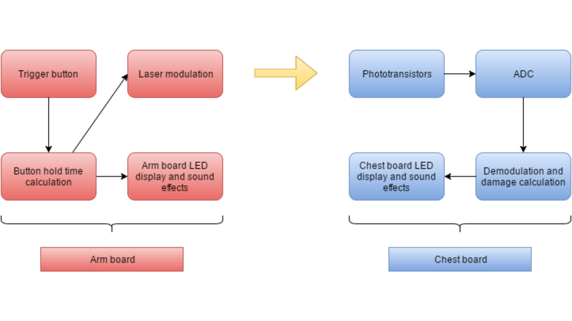
Each player wears two devices - one on their arm, and one on their chest. The arm board has an MSP430g2553 microcontroller for processing, a button that functions as the trigger, a laser for shooting, an LED strip to display energy, and a piezo buzzer for sound effects.
The chest board also has a MSP430g2553 for processing, a phototransistor array as the target, a ring of LEDs to display health, and a piezo buzzer for sound effects.
The design works as follows
- Player A presses the trigger button on the arm board and holds it for a length of time.
- As hold time increases, the shot powers up. The LED string on player A’s arm changes color to display power consumption upon button release.
- When player A releases the button, the laser on player A’s arm board fires and modulates at frequency to communicate the shot power.
- Player A consumes energy to fire the shot, and energy consumption is reflected in changes in the arm board’s LED display.
- If player A’s laser hits a phototransistor on player B’s chest board, the ADC in the MSP430 will register higher values and consequently a hit.
- Player B’s chest board demodulates by calculating modulation period.
- Player B takes damage associated with the modulation period and loses health.
- Player B’s chest board LEDs update to display remaining health, and the piezo buzzer plays the “you’ve been hit” sound effect.
The key aspect of this project is the communication between the laser on the arm board and the phototransistor array on the chest board. The following details our design of this project along with challenges and workarounds we implemented.
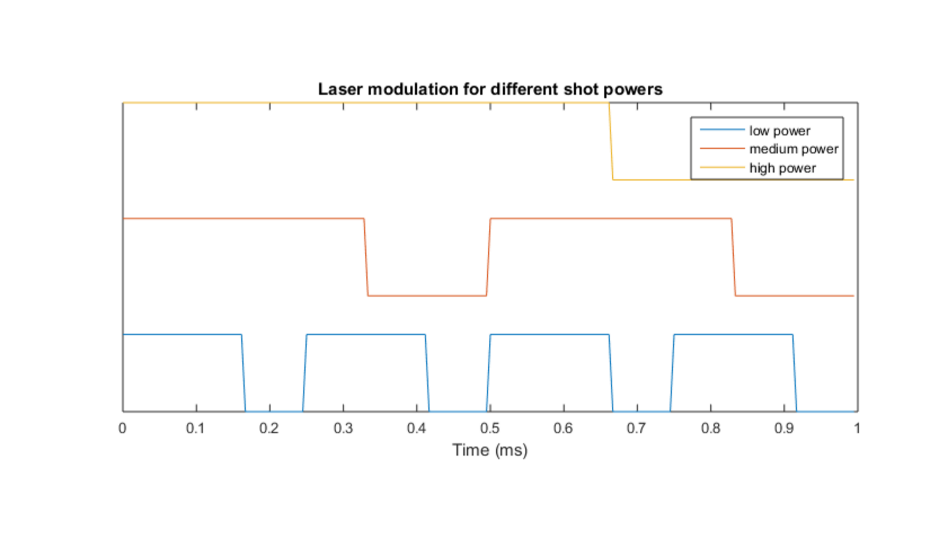
Laser modulation/demodulation
The laser is modulated at different frequencies to communicate shot power.
However, the MSP430g2553 only has two timer modules. One of them is used to control the piezo buzzer, and the other is used for SPI communication to the LED strips.
This leaves us having to implement the PWM output for the laser modulation in software.
At its fastest, the laser needed to modulate with a period of 0.25 milliseconds.
The microcontroller clock ran at 12 Mhz, the highest frequency possible when running on 3V. However, each cycle of the main loop also potentially required updating an LED display, debouncing the trigger button, calculating button hold time, and playing sound effects.
The amount of operations required per cycle makes it impossible to complete a cycle in 0.25 milliseconds.
Therefore, laser modulation is performed in an interrupt. While having long interrupt routines is generally bad design, it is necessary in this case, and potential dangers of having long interrupt routines is offset by having only a watchdog interrupt.
Similarly, demodulation on the chest board is also performed in the watchdog interrupt. The processor records the time between rising and falling edges detected by the phototransistor array. Transition time is summed up across 16 transitions to calculate the modulation time and corresponding damage received.
Phototransistor sensors
Each chest board has an array of five phototransistors. The transistors used in this project are PT33406C NPN transistors by Everlight. In their off state, their output is connected to ground by a pull-down resistor. When light from the laser hits them,the output voltage increases depending on luminosity.
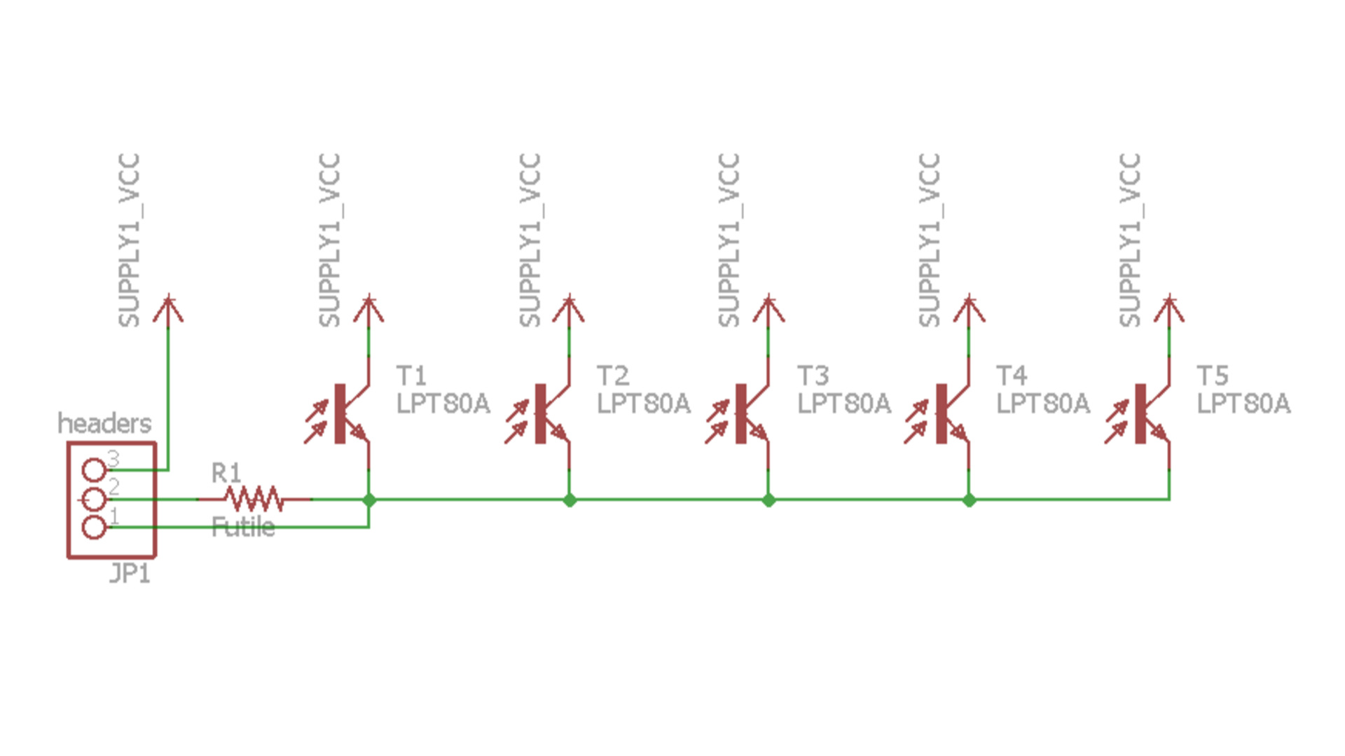
However, since the voltage increase isn’t always large enough to be read as a digital high, we configure the input pin to send the data to the ADC10.
Upon startup, the ADC10 automatically calibrates itself and calculate a base value.
Hysteresis is performed in detecting hits by the laser. To initially register a hit by the laser, the ADC must read out an value of at least base + 25. Further ADC values must be at least base + 15 to register as high. Values below will be registered as low.
User Interface
The arm and chest boards both use a combination of LEDs and a piezo buzzer to convey information to the user. The chest board emits a tune on startup, and plays a tone every time it registers damage. When the player’s health has reached 0, it plays a “game over” tune. It must then be power cycled in order to play again.
The arm board also plays a tune upon startup. When the user holds the trigger, a tone of increasing pitch will sound, with the pitch dependant upon the power of the shot. The board will trill when the button is released to indicate that it is firing. There is also feedback if the user attempts to fire but is out of energy, and when the energy has fully recharged. The LED strip on the arm board displays current energy, and energy to be used when firing.